Transformer Principles and Applications
Transformer Principles and Applications
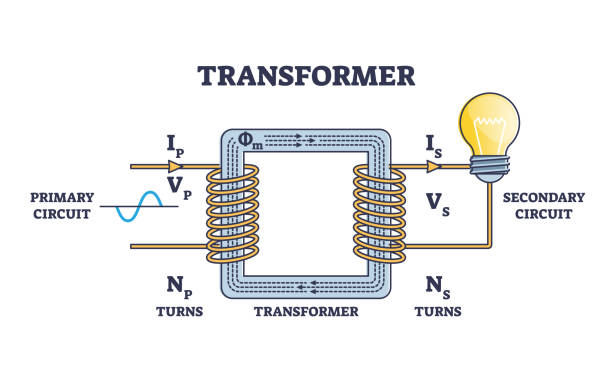
(Schematic: Primary and secondary coils in an ideal transformer structure)
I. Core Principles of Transformers
1.1 Engineering Implementation of Electromagnetic Induction
Transformers operate based on Faraday's Law of Electromagnetic Induction, achieving voltage/current conversion through coil turn ratios. When alternating current flows through the primary coil, the changing magnetic field induces electromotive force (EMF) in the secondary coil. The fundamental relationship is:
\frac{V_p}{V_s} = \frac{N_p}{N_s}Where [V_p] and [V_s] represent primary/secondary voltages, and [N_p]/[N_s] denote coil turns. The turn ratio directly determines step-up/step-down characteristics:
- Step-Up Transformer:
N_s > N_p(e.g., power transmission systems)
- Step-Down Transformer:
N_s < N_p(e.g., smartphone chargers)
1.2 Power Conservation and Loss Mechanisms
Under ideal conditions, [P_p = P_s] (input power = output power). Combining this with Ohm's Law yields the current relationship:
\frac{I_p}{I_s} = \frac{N_s}{N_p}Real-world applications must account for copper losses (resistive heating in windings) and iron losses (hysteresis/eddy current losses), with typical efficiency ranging 95-99%. For example, a transformer with 100W input and 98% efficiency delivers:
P_{out} = 100W \times 0.98 = 98WII. Practical Problem Solving
2.1 Voltage Calculation Example
A transformer has 200 primary turns and 1000 secondary turns with 120V input. Calculate the output voltage.
Solution:
\frac{120}{V_s} = \frac{200}{1000} \Rightarrow V_s = 600V2.2 Current & Efficiency Analysis
The above transformer drives a 10Ω load with 95% efficiency. Find the primary current.
Step-by-Step Solution:
- Secondary current:
I_s = \frac{600V}{10Ω} = 60A- Theoretical power:
P_s = 600V \times 60A = 36kW- Actual input power:
P_p = \frac{36kW}{0.95} ≈ 37.89kWs 4. Primary current:
I_p = \frac{37890W}{120V} ≈ 315.75AIII. Key Engineering Parameters
3.1 Design Specifications
| Parameter | Typical Range | Design Considerations |
|---|---|---|
| Turn Ratio | 1:1 ~ 1:100 | Voltage conversion requirements |
| Wire Diameter | 0.1-5mm | Current capacity & space constraints |
| Core Material | Silicon Steel/Ferrite | Frequency response & loss characteristics |
3.2 Efficiency Optimization Strategies
- Laminated Core Design: 0.3mm silicon steel laminations reduce eddy current losses by 40%
- Litz Wire Technology: Multi-stranded conductors minimize skin effect in high-frequency applications
- Liquid Cooling: Oil-immersion cooling boosts efficiency by 2-3% in high-power transformers
IV. Emerging Technologies
- High-Temperature Superconducting (HTS) Transformers: Achieve >99.5% efficiency using YBCO superconducting tapes
- Smart Voltage Regulation: IGBT-based electronic transformers with <1ms response time
- Wireless Power Transfer: Magnetic resonance coupling breaks traditional coil limitations
Conclusion
As the cornerstone of electromagnetic energy conversion, transformer design fundamentally balances material properties, spatial constraints, and energy efficiency. Mastering these principles not only aids circuit design but also reveals the underlying logic of modern power systems—from power plants to smartphone chargers, transformers silently sustain the energy infrastructure of human civilization.